Arduino Demystified
Arduinos! Everyone’s favorite toy for random electronics projects. But honestly, it really doesn’t feel like you learn a lot about the hardware. Most of the time you grab a library and it does magical stuff for you, all you do is plug stuff together and use other libraries.
There are libraries for everything from servo motors to ethernet and SD cards. You really don’t need to know much about the Arduino hardware or even the peripherals in order to make functional programs. That’s the beauty of an Arduino.
Now let’s strip away all of those niceties and learn how to suffer through the hardware details. I say suffer, but this is how you’ll use many other microcontrollers. Also, you may need to know this to write a library yourself. So here’s a bit of information that I wish I could find in one place more easily.
What programming language?
You can write code for Arduino in any language. It’s just about targeting the AVR CPU and loading it on the chip. But, the Arduino IDE uses C++.. kind of.
When you first load up the IDE, you get a file like this:
void setup() {
  // put your setup code here, to run once:

}

void loop() {
  // put your main code here, to run repeatedly:

}
Obviously, that’s not a “normal” C++ program - where’s main?
Turns out, you can find this and a lot more from the ArduinoCore-avr project on Github. Just search main in that repo and you’ll find main.cpp. That has the following as its main function:
main.cpp
int main(void)
{
	init();

	initVariant();

#if defined(USBCON)
	USBDevice.attach();
#endif

	setup();

	for (;;) {
		loop();
		if (serialEventRun) serialEventRun();
	}

	return 0;
}
So, along with some extra stuff, it calls our setup and loop functions we saw before. So that’s how it all ties together - magic that we have no way of seeing how it’s called or what its context is! Well that’s fine for beginners I suppose, and at least it’s open source so people like me can look at what happens.
So yes, Arduino uses C++ (the file with main is a .cpp file!), but it’s simplified a bit for development on a tiny computer.
Blink!
The first program you will write on basically any microcontroller is “blink” - just where you blink an LED on and off. Here’s what the Arduino IDE gives as an example:
Blink
// the setup function runs once when you press reset or power the board
void setup() {
  // initialize digital pin LED_BUILTIN as an output.
  pinMode(LED_BUILTIN, OUTPUT);
}

// the loop function runs over and over again forever
void loop() {
  digitalWrite(LED_BUILTIN, HIGH);  // turn the LED on (HIGH is the voltage level)
  delay(1000);                      // wait for a second
  digitalWrite(LED_BUILTIN, LOW);   // turn the LED off by making the voltage LOW
  delay(1000);                      // wait for a second
}
So, we have the setup and loop functions we saw before. In setup we run one time code: pinMode(LED_BUILTIN, OUTPUT) - sets the builtin LED to an output (as opposed to an input that we may read high/low, like a button). Then the loop function just sets that LED high, waits a second, then low, and waits another second. Easy!
Now, these sorts of functions aren’t included in a header file like normal in C++ - we don’t see a new include at the top. Where is it? Actually, we get it from an auto-included file Arduino.h. We can see stubs for functions we used such as pinMode:
Arduino.h
void pinMode(uint8_t pin, uint8_t mode);
Or digitalWrite:
Arduino.h
void digitalWrite(uint8_t pin, uint8_t val);
And even delay:
Arduino.h
void delay(unsigned long ms);
Cool! If you’re less inclined to search through header files that are magically included without your say-so, these are also documented in the Arduino library reference.
It’d be pretty boring to just run through that file and explain how everything works. Instead, we’ll build it up ourselves and check out some Arduino code every so often. Sound good? Cool.
Registers
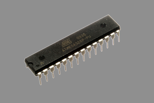
For the remainder of this post, I’m going to refer to a few things. First, the ATmega238P datasheet (henceforth just “datasheet”). This is the actual core microcontroller that powers an Arduino Uno - note it’s more than the CPU! This is what does most of the control, from pins to memory. The Arduino just adds some nice to haves on top. Why? Well, look at this:
If you’ve never worked with electronics or PCBs, you probably don’t even know where to start for this. Not exactly the best for quick education or prototyping, is it?
So we have a datasheet for the underlying microcontroller for an Arduino Uno. The main purpose for this is to give us register information. This includes registers like the stack pointer (split between SPH and SPL) and general purpose registers for arithmetic (R0 through R31). Each of these registers are 1 byte (8 bits). Some can get combined for certain operations, but we won’t deal with that.
We care more about the registers associated with I/O ports. In the datasheet, that’s section 13. I’ll try to translate it into simpler terms.
Each pin has three associated registers. These registers are split into different “ports” because there are more than 8 pins in each. The pin is associated with one bit from each of the three registers for a given port.
We’ll get to how to go from pin to its associated registers in a minute, but for now: pin 13 is associated with port B, bit 5. We then have three specific registers that we can manipulate bit 5 in order to achieve certain affects:
1) PORTB - section 13.4.2 in the datasheet. This controls what we send the pin - a high or low voltage.
2) DDRB - section 13.4.3 in the datasheet. This controls the direction of the pin - whether it’s input (0) or output (1).
3) PINB - section 13.4.4 in the datasheet. This gets set based on the value on the pin - it reads a high or low voltage.
For more information on each of those, feel free to read about what they mean in general in section 13.2.1 in the datasheet, since I’ll skip over some parts.
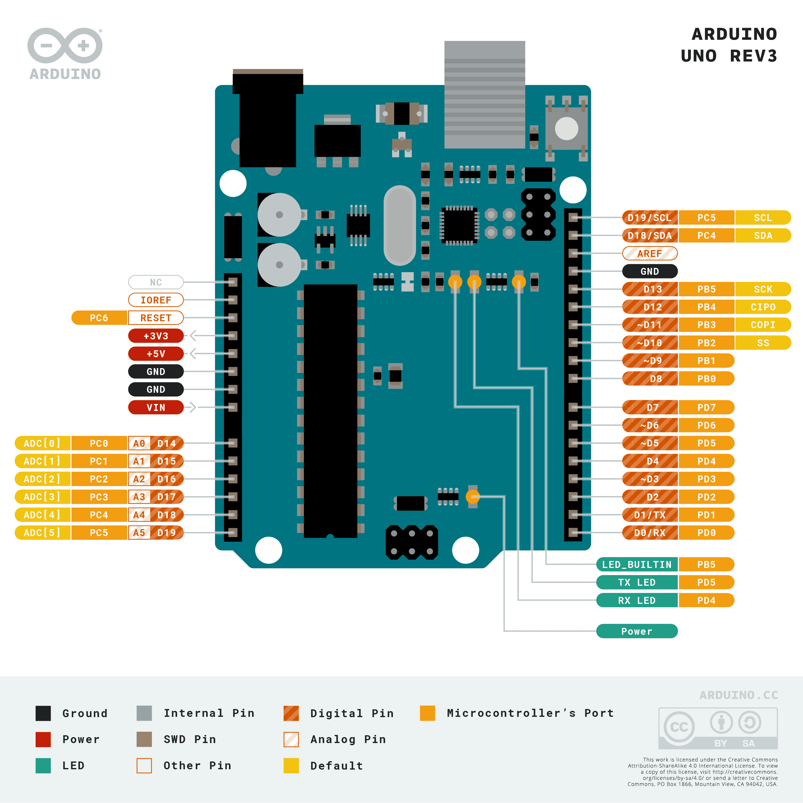
So now we have the three registers that will let us change that pin. How did we get those specific registers? Well, the easiest way is to find a pinout for the Arduino Uno and use that. There are very detailed pinout diagrams, but here’s a pretty simple one that gives everything we need right now:
Just look at pin D13 (D for digital) - next to it is PB5, which means port B pin 5. Easy enough.
With that background, we can go through each of the abstractions in our blink program and replace it with the harder to understand register manipulation!
digitalWrite and pinMode
Alright, so let’s redo digitalWrite. We know we have port B pin 5. The register associated with that is the first of three we described earlier - PORTB. We’re writing an output bit, that’s it. For now let’s do something hacky and just get it working.
So how do we do that? Let’s just change loop to set bit 5 (where bit 0 is the least significant bit) and unset it and see if that blinks it:
Blink
void loop() {
  PORTB = 0b100000;
  delay(1000);
  PORTB = 0;
  delay(1000);
}
Turns out, that works! We set the 5th bit, delay, unset it, then delay. That blinks the LED. Wow!
It may be useful to note that PORTB is not defined in the Arduino standard library I pointed to earlier. It’s actually in the libc implementation for AVR. This makes sense because PORTB is a register for the AVR microcontroller, not specific to Arduinos. Anything that uses the AVR microcontroller will need that. This will be the case for all of the registers I mention, so I won’t go through them again.
The pinMode function is also similarly easy. This sets the direction - if it’s input, the bit will be 0, if it’s output, the bit will be 1. That’s why when you make the inevitable mistake to not set a pin to output, nothing happens, but you’ll magically be able to use it as input - they default to zeroed out, which is input.
Turns out, the setup function with the new pin is pretty easy. We saw above that the register DDRB is associated with direction for pin 13. So.. let’s just set bit 5 the same way we did with PORTB:
Blink
void setup() {
  DDRB = 0b100000;
}
And it’s that easy.
Now, let’s work towards getting this to work for all pins.
Generalizing digitalWrite for all pins
At this point, we’ll look at the Arduino’s standard library. That’s because the pin to register mapping is not done by AVR, but by the Arduino library. We could do these mapping ourselves, but it turns out the Arduino standard library has a couple useful functions.
The first is in the standard Arduino.h file included in all Arduino sketches: a macro called digitalPinToPort. Well, it’s exactly what you think it is, it gives you the port from a pin. It’s defined as:
Arduino.h
#define digitalPinToPort(P) ( pgm_read_byte( digital_pin_to_port_PGM + (P) ) )
Then with that, you can use one of three macros to get a pointer to the register you need, whether it’s for output (like PORTB), direction (like DDRB), or input (like PINB):
Arduino.h
#define portOutputRegister(P) ( (volatile uint8_t *)( pgm_read_word( port_to_output_PGM + (P))) )
#define portInputRegister(P) ( (volatile uint8_t *)( pgm_read_word( port_to_input_PGM + (P))) )
#define portModeRegister(P) ( (volatile uint8_t *)( pgm_read_word( port_to_mode_PGM + (P))) )
Easy enough. Then, to get the specific bit.. well, it turns out we have that too:
Arduino.h
#define digitalPinToBitMask(P) ( pgm_read_byte( digital_pin_to_bit_mask_PGM + (P) ) )
Alright, with that, we now need to set or clear a specific bit. That’s just simply bit manipulation. If you want to set bit 5 without changing other bits, you may use a bitwise | (or). This will set that bit no matter what, then keep all of the others the same. So to do that for bit 5:
PORTB |= 0b100000;
Then to toggle it off, you can bitwise & (and) the complement (all bits flipped). Like so:
PORTB &= ~0b100000;
So that ends up being PORTB &= 0b11011111 - this will always clear the bit with 0 (which is bit 5, as desired) and keep the other values for each other bit.
So to generalize digitalWrite, we’ll use the same signature:
Blink
void myDigitalWrite(uint8_t pin, uint8_t val) {
Then get the port, output pointer, and pin bit mask:
Blink
  uint8_t port = digitalPinToPort(pin);
  uint8_t *ptr = portOutputRegister(port);
  uint8_t bit = digitalPinToBitMask(pin);
Now we can just set the pin like before. We’ll use Arduino’s defined LOW (0) and HIGH (1). We’ll just do nothing if they pass a value other than that:
Blink
  if (val == HIGH) {
    *ptr |= bit;
  } else if (val == LOW) {
    *ptr &= ~bit;
  }
Then we’re done! Here’s the whole thing:
Blink
void myDigitalWrite(uint8_t pin, uint8_t val) {
  uint8_t port = digitalPinToPort(pin);
  uint8_t *ptr = portOutputRegister(port);
  uint8_t bit = digitalPinToBitMask(pin);

  if (val == HIGH) {
    *ptr |= bit;
  } else if (val == LOW) {
    *ptr &= ~bit;
  }
}
We can use it like:
Blink
void loop() {
  myDigitalWrite(LED_BUILTIN, HIGH);
  delay(1000);
  myDigitalWrite(LED_BUILTIN, LOW);
  delay(1000);
}
There we go, our own digitalWrite.
Aside: The real digitalWrite
Alright, it turns out there are a couple complications with digitalWrite that may come up in other places, so I’ll mention them here. For this, I will go through the whole digitalWrite function in the Arduino standard library. I promise it’s the only time I’ll do this.
First, the setup is similar to the one we made:
wiring_digital.c
	uint8_t timer = digitalPinToTimer(pin);
	uint8_t bit = digitalPinToBitMask(pin);
	uint8_t port = digitalPinToPort(pin);
	volatile uint8_t *out;
The out variable here is equivalent to the ptr variable I used. Note that theirs is marked volatile. That’s because this is a memory address that may be changed by something outside of this function. So the compiler shouldn’t say it knows some crazy compiler optimization here: act as though this variable may change without your knowledge. That way it will do what it’s told.
We alse declare timer which is used after:
wiring_digital.c
	if (port == NOT_A_PIN) return;

	// If the pin that support PWM output, we need to turn it off
	// before doing a digital write.
	if (timer != NOT_ON_TIMER) turnOffPWM(timer);
Well, first we abort if they pass something that’s not an Arduino pin, like 42.
Then, this condition is the only use of timer (set early). We’ll later get into what pulse width modulation (PWM) is and how it works. But, this is just a consequence of some pins being usable as pseudo-analog PWM pins. We should disable that functionality if we want a dumb on/off.
Next we set the out variable:
wiring_digital.c
out = portOutputRegister(port);
Just as we did with ptr. Easy.
Then we get some… stuff?
wiring_digital.c
	uint8_t oldSREG = SREG;
	cli();
Alright so that came out of no where, but no fret, these are easy. If we search for SREG in the datasheet above, we find:
SREG - AVR status register
So that’s SREG for S(tatus) Reg(ister). Simple. But why do we store the old value? Actually, the answer is in the bit 7 documentation:
The I-bit can also be set and cleared by the application with the SEI and CLI instructions, as described in the instruction set reference.
So cli is just an instruction that clears the I-bit of the SREG register, which disables interrupts. Since an interrupt can come in at any time, we really really do not want that happening somewhere bad. It could happen after we read the register value, then we come back and do the operation with an old value!
Well, since cli is an instruction, it’s again in the AVR libc implementation:
interrupt.h
# define cli() __asm__ __volatile__ ("cli" ::: "memory")
Yeah so it basically just adds the cli instruction into the assembly.
So, going back to digitalWrite, why do we have to keep the old SREG value? Well, it’s just because we don’t want that interrupt disable to be permanent. Say the user has interrupts enabled and we disable them in digitalWrite - that would be bad. Then, we can’t just reenable them after digitalWrite - what if the user disabled them? Then every time they call digitalWrite their interrupts are reenabled - not cool. So we keep the value that it was called with. We’ll see later that this is reapplied.
Okay, back to regularly scheduled programming, here’s something familiar in the next lines of digitalWrite:
wiring_digital.c
	if (val == LOW) {
		*out &= ~bit;
	} else {
		*out |= bit;
	}
Yup, pretty similar to the set/unset we did (except this will always set it if val is not LOW - slightly different!)
And finally:
wiring_digital.c
SREG = oldSREG;
Yep so we restored the old SREG value.
It’s all pretty simple, even if there’s a bit of extra stuff we need to care about when dealing with the actual Arduino standard library. It’s important to do, but our dummy implementations don’t need to do all of that.
Speaking of dummy implementations of Arduino functions.. how about we read some inputs?
Inputs
Alright so that was a lot just for the most basic function that you can do with an Arduino. There’s absolutely no way that input is that much.
… Actually, yeah, it’s a bit simpler and we have all the tools for doing this now. But first, let’s take a detour to wire something up since we don’t have a builtin input method like we do with a builtin LED.
For this we’ll just grab Arduino’s Button example, which puts the button on pin 2. I won’t show any videos or anything of it working after each step, just believe me. But here’s a picture of my Arduino with a button on pin 2:
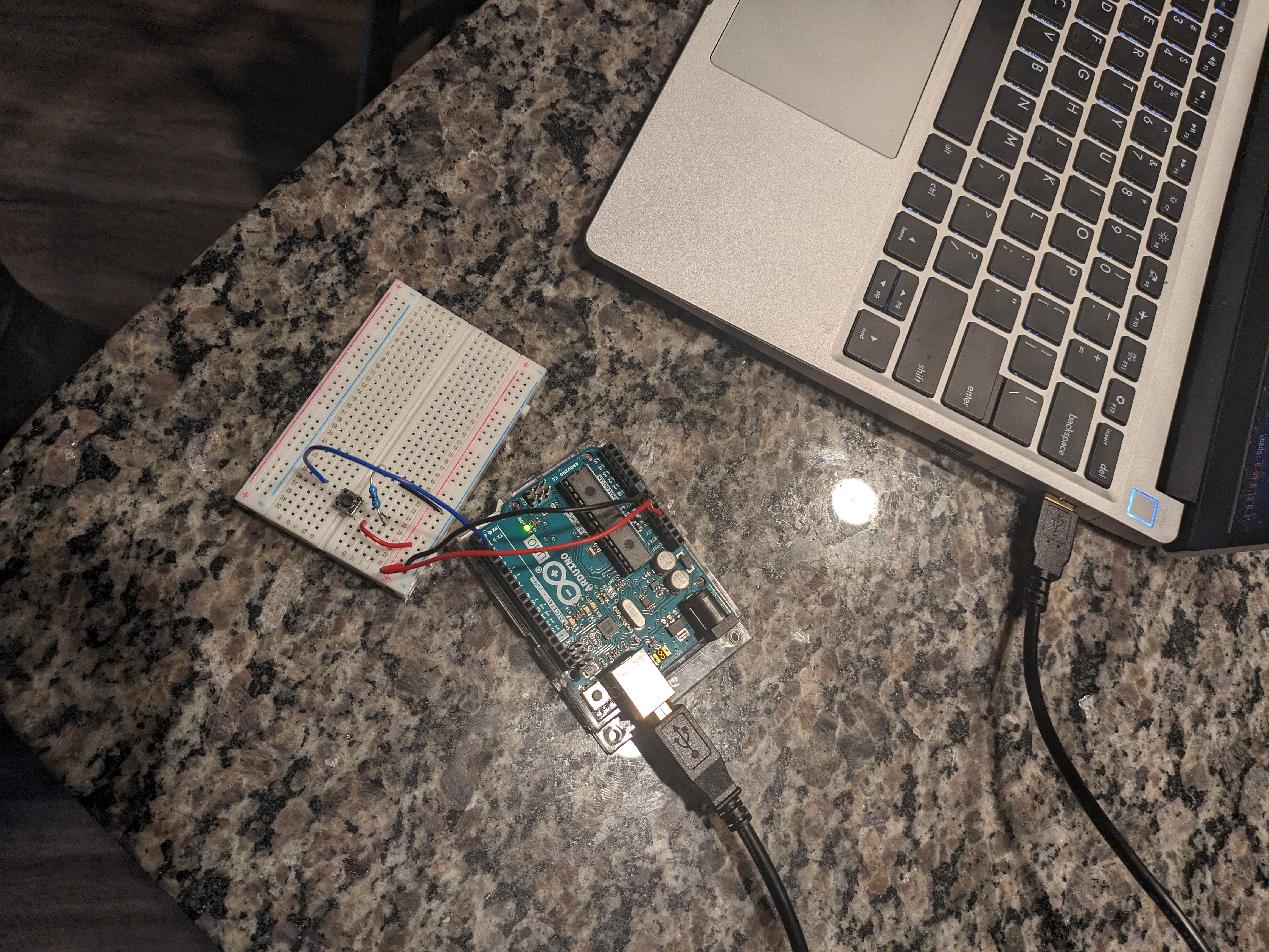
And here’s me pressing the button. If you hold your screen really close, you may see a small LED on the Arduino light up.
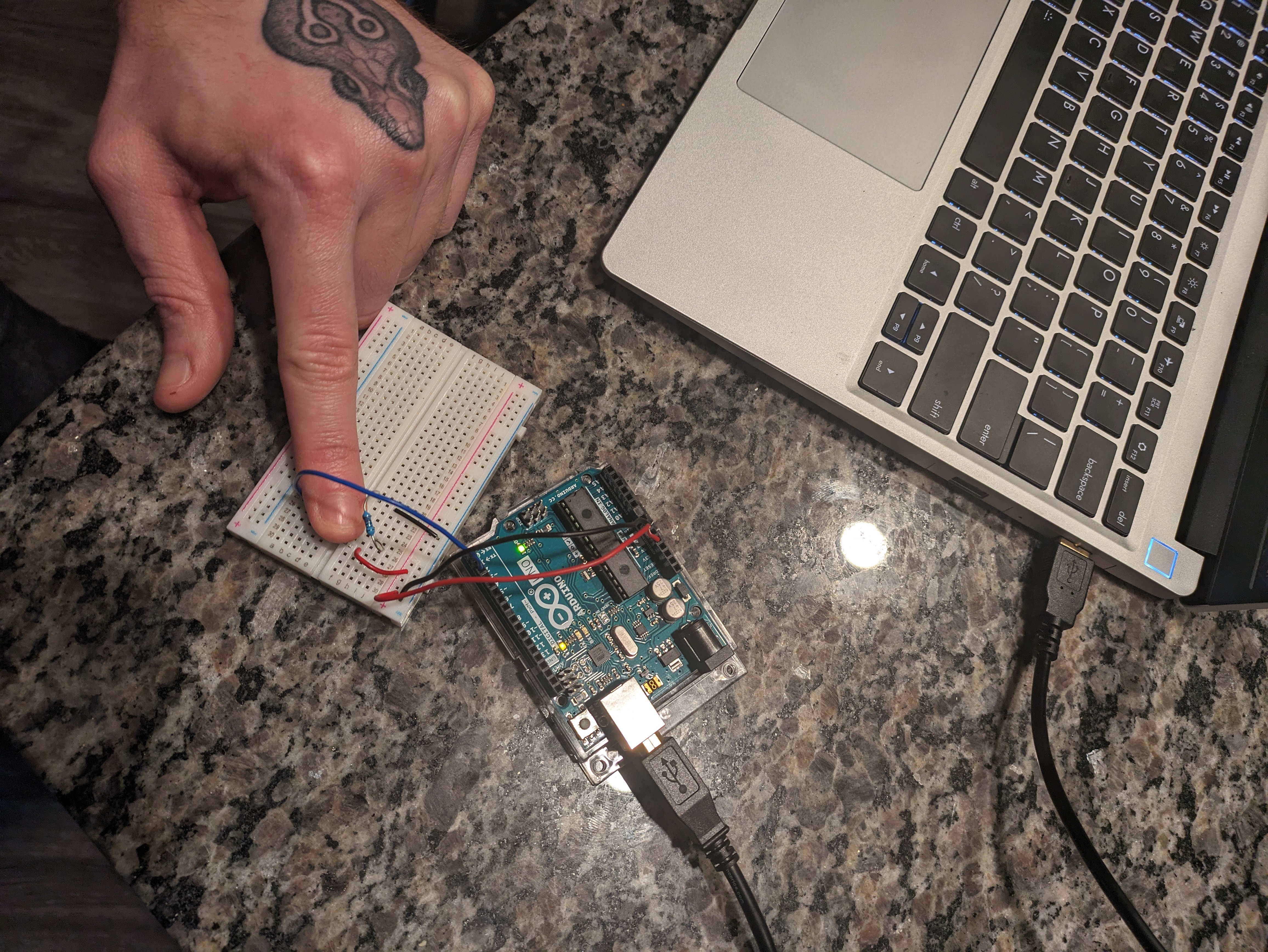
Incredible! Here’s the code that comes with the Button example:
Button
const int buttonPin = 2;  // the number of the pushbutton pin
const int ledPin = 13;    // the number of the LED pin

// variables will change:
int buttonState = 0;  // variable for reading the pushbutton status

void setup() {
  // initialize the LED pin as an output:
  pinMode(ledPin, OUTPUT);
  // initialize the pushbutton pin as an input:
  pinMode(buttonPin, INPUT);
}

void loop() {
  // read the state of the pushbutton value:
  buttonState = digitalRead(buttonPin);

  // check if the pushbutton is pressed. If it is, the buttonState is HIGH:
  if (buttonState == HIGH) {
    // turn LED on:
    digitalWrite(ledPin, HIGH);
  } else {
    // turn LED off:
    digitalWrite(ledPin, LOW);
  }
}
So we care about one thing: the digitalRead function at the beginning of the loop function. Can we rewrite that line?
Well, we know from before that it will be in a register, just we’ll read from the register, not write. According to the handy pinout diagram I showed before, pin 2 is port D bit 2. The input register, then, is PIND. So 0b100 should be a proper bitmask on PIND.
Here’s a simplification: we could bitshift this right twice to get a 0 or 1 - or, we could just ask “is this above 0?” and if it is, that pin is high! If so, we’ll turn it into 1 (because I don’t want to touch the rest of the code that assumes it’s a 0 or 1), if not then we’ll just keep it 0. So we can change setting buttonState like so:
Button
  int pinVal = PIND & 0b100;
  buttonState = pinVal > 0;
Well.. that was easy. So look, not only can we write from registers, we can also read them! Memory!
Now we can make our own digitalRead like before, and it’s actually a bit easier in my opinion. Here’s the whole thing:
Button
int myDigitalRead(uint8_t pin) {
  uint8_t port = digitalPinToPort(pin);
  uint8_t *ptr = portInputRegister(port);
  uint8_t bit = digitalPinToBitMask(pin);
  return (*ptr & bit) > 0;
}
So we start with the same thing, just changing ptr to come from portInputRegister rather than portOutputRegister. Then, we just test if the bit value is greater than 0. Note that we’re kind of assuming that HIGH is 1 and LOW is 0, which may not always be true, but it works for now so who cares.
Now how about the real thing? Well it’s also a little easier:
wiring_digital.c
int digitalRead(uint8_t pin)
{
	uint8_t timer = digitalPinToTimer(pin);
	uint8_t bit = digitalPinToBitMask(pin);
	uint8_t port = digitalPinToPort(pin);

	if (port == NOT_A_PIN) return LOW;

	// If the pin that support PWM output, we need to turn it off
	// before getting a digital reading.
	if (timer != NOT_ON_TIMER) turnOffPWM(timer);

	if (*portInputRegister(port) & bit) return HIGH;
	return LOW;
}
So we have the same stuff as digitalWrite: Return if the pin isn’t a real pin and turn off PWM if necessary. But we don’t do any nonsense around interrupts - we just read the pin, test it, and return HIGH or LOW.
Disabling interrupts is not necessary here - loading the value of that register is a single instruction. With digitalWrite, we read a value, used it, then set it again. If there was an interrupt between the read and write, we may get an issue. Here we just have one instruction and don’t write back to it, so no risk of that. It makes it nice and simple.
Now that we have the two fundamental operations, we need to get the way to go between them working.
pinMode, Revisited
In the digitalWrite section, we had to put something hacky for pinMode, but it has some complications I wanted to address after showing how to make digitalRead. It’s time!
In theory, pinMode is also super easy. It’s just digitalWrite but with a different port:
Blink
void myPinMode(uint8_t pin, uint8_t mode) {
  uint8_t port = digitalPinToPort(pin);
  uint8_t *ptr = portModeRegister(port);
  uint8_t bit = digitalPinToBitMask(pin);

  if (mode == OUTPUT) {
    *ptr |= bit;
  } else if (mode == INPUT) {
    *ptr &= ~bit;
  }
}
Then, as with HIGH and LOW values for digitalWrite, we can find OUTPUT and INPUT in Arduino.h:
Blink
#define INPUT 0x0
#define OUTPUT 0x1
#define INPUT_PULLUP 0x2
Wait, there’s also INPUT_PULLUP, what’s that?
Pull-up resistors
Well, here’s Arduino’s documentation on the pull up mode. It’s just an internal pull-up resistor. These are used to prevent a “floating” value, where the input value may be anywhere between ground or high because it’s not connected to either!
The button is wired slightly differently, where pin 2 will read a floating value if the button is not pressed, or 0 if it is. This means it’s inverted logic compared to what we had before. Here’s Arduino’s “DigitalInputPullup” example for a reference:
DigitalInputPullup
void setup() {
  //start serial connection
  Serial.begin(9600);
  //configure pin 2 as an input and enable the internal pull-up resistor
  pinMode(2, INPUT_PULLUP);
  pinMode(13, OUTPUT);
}

void loop() {
  //read the pushbutton value into a variable
  int sensorVal = digitalRead(2);
  //print out the value of the pushbutton
  Serial.println(sensorVal);

  // Keep in mind the pull-up means the pushbutton's logic is inverted. It goes
  // HIGH when it's open, and LOW when it's pressed. Turn on pin 13 when the
  // button's pressed, and off when it's not:
  if (sensorVal == HIGH) {
    digitalWrite(13, LOW);
  } else {
    digitalWrite(13, HIGH);
  }
}
So the goal here is to get INPUT_PULLUP working.
How to pull-up?
The datasheet section 13.2.3 has a nice table (table 13-1), recreated here for your convenience:
| DDxn | PORTxn | PUD (in MCUCR) | I/O | Pull-up | Comment |
|---|---|---|---|---|---|
| 0 | 0 | X | Input | No | Tri-state (Hi-Z) |
| 0 | 1 | 0 | Input | Yes | Pxn will source current if ext. pulled low. |
| 0 | 1 | 1 | Input | No | Tri-state (Hi-Z) |
| 1 | 0 | X | Output | No | Output low (sink) |
| 1 | 1 | X | Output | No | Output high (source) |
Okay, most of this doesn’t matter for what we’re going towards, but compare the one row marked “Input” and “Pull-up” and the two marked “Input” without “Pull-up” - ignoring the PUD column so the two in common are basically the same. The difference is PORTxn - that’s the output register!
So the myPinMode function written above doesn’t address the output values for simplicity, but really it matters. So let’s make that change.
The final custom myPinMode
I’ll go by step by step again.
The first part is pretty predictable, with some different variable names for clarity:
DigitalInputPullup
void myPinMode(uint8_t pin, uint8_t mode) {
  uint8_t port = digitalPinToPort(pin);
  uint8_t *modeReg = portModeRegister(port);
  uint8_t *outReg = portOutputRegister(port);
  uint8_t bit = digitalPinToBitMask(pin);
Then we have output:
DigitalInputPullup
  if (mode == OUTPUT) {
    *modeReg |= bit;
Cool, it’s the same since the output value can just stay the same. Input is the same, but we clear the output register bit too:
DigitalInputPullup
  } else if (mode == INPUT) {
    *modeReg &= ~bit;
    *outReg &= ~bit;
And, predictably, pull-up input just sets outReg too:
DigitalInputPullup
  } else if (mode == INPUT_PULLUP) {
    *modeReg &= ~bit;
    *outReg |= bit;
  }
}
And that’s the end of the function! Incredible.
The real pinMode?
Okay, I’ll just go through differences with the real pinMode and not step through the whole thing.
First, before calling portModeRegister and portOutputRegister, there’s a check to make sure it’s a pin:
wiring_digital.c
if (port == NOT_A_PIN) return;
Then, each case has a caching of the SREG register and stopping interrupts, then restoring, like digitalWrite. Here’s the INPUT logic as an example:
wiring_digital.c
uint8_t oldSREG = SREG;
cli();
*reg &= ~bit;
*out &= ~bit;
SREG = oldSREG;
Leading whitespace for these snippets was fixed for your viewing pleasure.
And that’s about all of the differences we have. All in all, it wasn’t that bad. But now we’re going to go into something more complicated than just turning something off and on - turning something off and on in rapid succession!
PWM
Pulse width modulation (PWM) is a way to “fake” analog output from a digital source. If you can only output 5 volts, but you want 3 volts output, how can you do that? Well if you’re at 5 volts 3/5 of the time, then there you go. That’s (roughly) PWM.
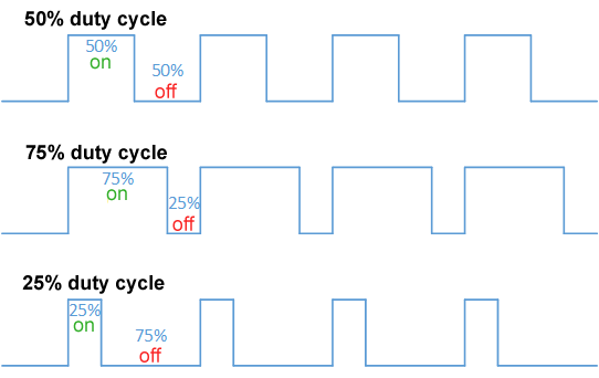
The two variables you need to know are the duty cycle and the period (or its reciprocal, frequency). The duty cycle is what percentage of time you’re “on” - so our example above would be 3/5 = 60% duty cycle. The period is how long a duty cycle takes to complete - this would generally be too small for us to see.
Here’s a nice handy picture ripped straight from the Wikipedia article I linked above:
PWM in action
Normally I’d use Arduino’s example, but the example for analogWrite is a bit more complex than I really care for. I just want to show you a dim LED. Here’s the code to make a dim LED:
SimpleAnalogWrite
void setup() {
  // Pin 3 is the first PWM pin on Uno
  pinMode(3, OUTPUT);
}

void loop() {
  analogWrite(3, 50);
}
It’s pretty simple! The analogWrite function takes the pin (3) and the duty cycle, expressed as a number from 0-255. So 50 would be a 50/255 = 19.6% duty cycle.
Here’s a comparison between using 50 (left) and 200 (right) for the value:
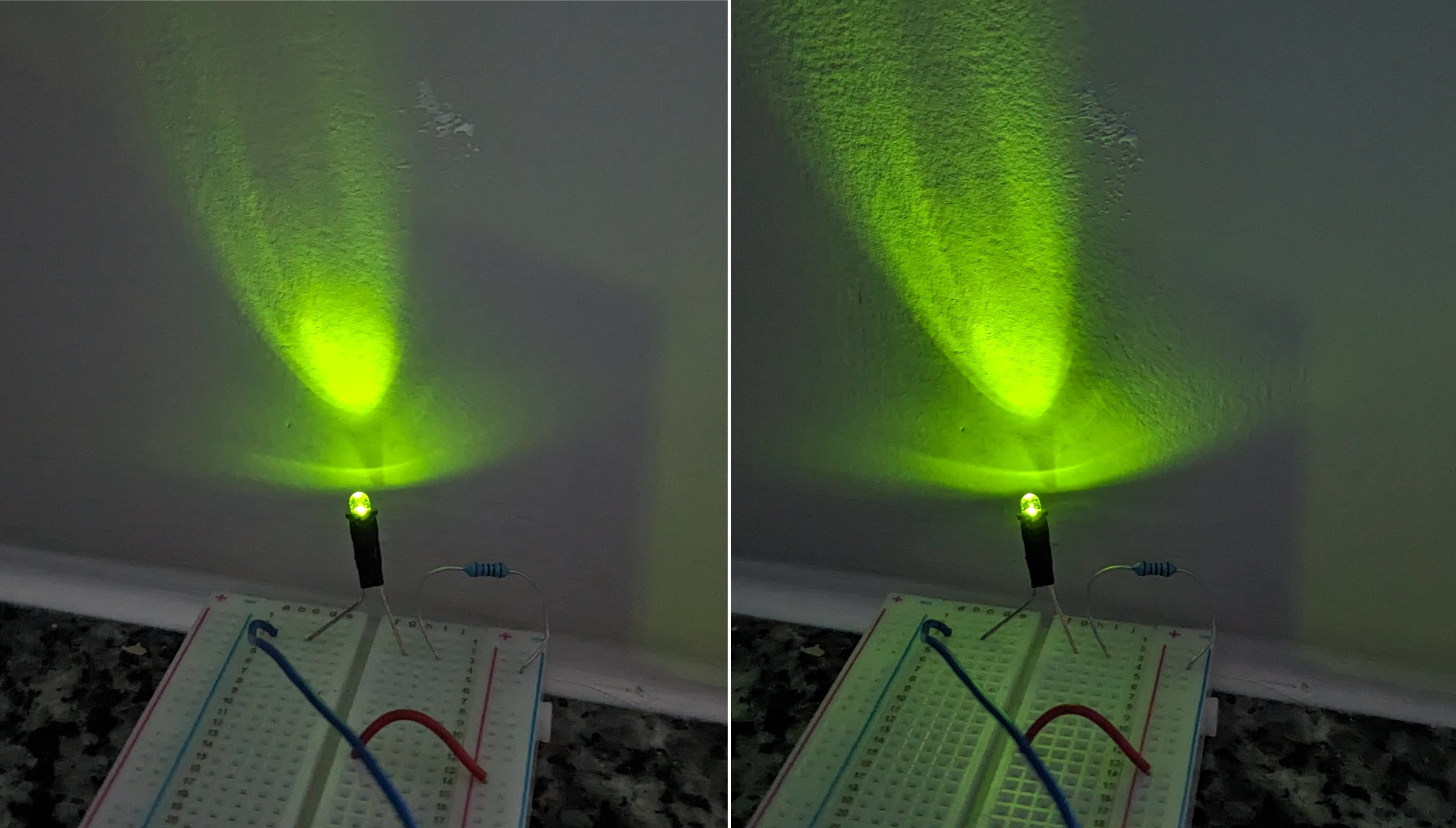
Well it’s not a super drastic difference, but that’s expected considering we see increases in brightness logarithmically. Doubling the brightness will seem like a constant increase. Obviously, I’m not an eye scientist, though.
If you want a clearer example of the difference, here’s a 5/255 = 1.9% duty cycle:
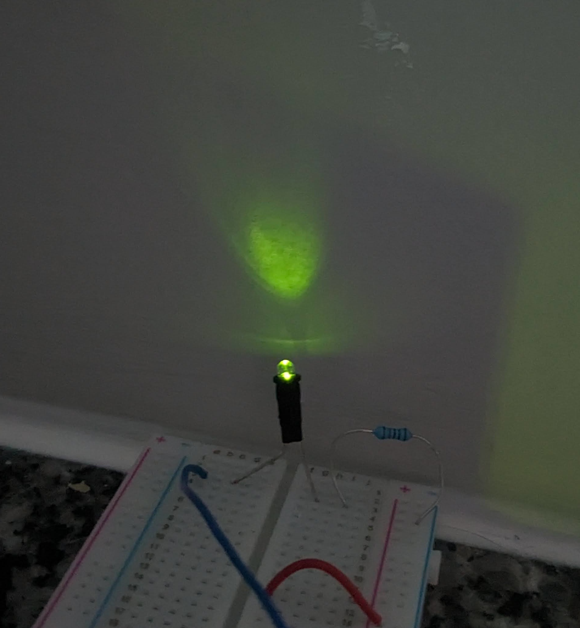
Obviously, a fair bit dimmer.
As a side note, I got this LED for free, but apparently it was something like $20 USD. That’s really strange to me.
Okay, now we’ve seen PWM in action! Now let’s get into the low-level stuff, as is my want.
Our PWM interface: more registers!
Now, Arduino defines the PWM frequency for you. Each pin may be different. For example, pin 3 will be 490 Hz while pin 5 will be 980 Hz. That means 490 or 980 cycles of the (puny) 16 MHz frequency.
It gets a little funky here. There’s a really good reference in the Arduino docs for timers and how that affects PWM on the Arduino. I, however, won’t go into all of it. I’ll try to keep it as simple as possible - feel free to check that out if you want a detailed explanation.
PWM on Arduino is attached to various timers in the CPU. There are three such timers. For the following register names, replace ‘x’ with a timer number (0, 1, 2):
1) TCCRxA - The control register, where you set/clear bits in order to enable/disable certain modes and whatnot
2) TCCRxB - Basically the same thing as above but with more options
3) TCNTx - The actual timer value of timer X
4) OCRxA/OCRxB - Output compare register. This gets continuously compared with TCNTx in order to trigger events like interrupts
5) TIMSKx - Interrupt mask register, primarily used to enable interrupts for PWM
6) TIFR0 - More data on the timer! Like overflows and matches
We care about TCCRxA and TCCRxB when enabling/disabling PWM. OCRxA and OCRxB will be used to set the duty cycle. The rest just have one time setup or other uses that we won’t look into.
Okay, with all of that background, we can understand the analogWrite function!
Arduino’s analogWrite
I won’t go into every line in detail since there’s a lot of repetition for other chips and whatnot. The beginning of the function is pretty easy to understand from the rest of what we’ve looked at:
wiring_analog.c
// Right now, PWM output only works on the pins with
// hardware support.  These are defined in the appropriate
// pins_*.c file.  For the rest of the pins, we default
// to digital output.
void analogWrite(uint8_t pin, int val)
{
	// We need to make sure the PWM output is enabled for those pins
	// that support it, as we turn it off when digitally reading or
	// writing with them.  Also, make sure the pin is in output mode
	// for consistenty with Wiring, which doesn't require a pinMode
	// call for the analog output pins.
	pinMode(pin, OUTPUT);
	if (val == 0)
	{
		digitalWrite(pin, LOW);
	}
	else if (val == 255)
	{
		digitalWrite(pin, HIGH);
	}
	else
	{
Basically, values of 0 and 255 are just aliased to digitalWrite calls, but you don’t need to call pinMode first.
The rest of this function is a big switch statement. For this, I’ll just omit a lot - that will be marked with // ... to signify it is skipped.
wiring_analog.c
switch(digitalPinToTimer(pin))
{
    // ...

	#if defined(TCCR0A) && defined(COM0A1)
	case TIMER0A:
		// connect pwm to pin on timer 0, channel A
		sbi(TCCR0A, COM0A1);
		OCR0A = val; // set pwm duty
		break;
	#endif

    // ...

	case NOT_ON_TIMER:
	default:
		if (val < 128) {
			digitalWrite(pin, LOW);
		} else {
			digitalWrite(pin, HIGH);
		}
}
So we have a big switch on the timer (from digitalPinToTimer(pin)) where we set some COM bit in the TCCRx register. All that does is enable the OCRx comparison at the hardware level. Then, we set the OCRxA register to the duty cycle provided (which is just a value from 1 to 254, since we filtered out the extremes before).
A small note is the default in the switch just sets it to low if below 128 and high otherwise. This may happen if we try calling this on a pin without PWM. Kind of weird in my opinion, but what else would you do?
Aside: Where is digitalPinToTimer?
We’ve seen a couple of “functions” like this from Arduino.h, like digitalPinToPort, for example. But I haven’t explained where those come from. So here we go.
We can find the function-like macro digitalPinToTimer in Arduino.h:
Arduino.h
#define digitalPinToTimer(P) ( pgm_read_byte( digital_pin_to_timer_PGM + (P) ) )
It gets the value from digital_pin_to_timer_PGM, whose declaration is just above that:
Arduino.h
extern const uint8_t PROGMEM digital_pin_to_timer_PGM[];
Well, it’s extern, so we don’t have it here. Where does that live? It’s actually in the same repo - just in the variants directory. Each variant has a pins_arduino.h file. In the standard variant, we can find this:
variants/standard/pins_arduino.h
const uint8_t PROGMEM digital_pin_to_timer_PGM[] = {
	NOT_ON_TIMER, /* 0 - port D */
	NOT_ON_TIMER,
	NOT_ON_TIMER,
	// on the ATmega168, digital pin 3 has hardware pwm
#if defined(__AVR_ATmega8__)
	NOT_ON_TIMER,
#else
	TIMER2B,
#endif
	NOT_ON_TIMER,
	// on the ATmega168, digital pins 5 and 6 have hardware pwm
#if defined(__AVR_ATmega8__)
	NOT_ON_TIMER,
	NOT_ON_TIMER,
#else
	TIMER0B,
	TIMER0A,
#endif
	NOT_ON_TIMER,
	NOT_ON_TIMER, /* 8 - port B */
	TIMER1A,
	TIMER1B,
#if defined(__AVR_ATmega8__)
	TIMER2,
#else
	TIMER2A,
#endif
	NOT_ON_TIMER,
	NOT_ON_TIMER,
	NOT_ON_TIMER,
	NOT_ON_TIMER, /* 14 - port C */
	NOT_ON_TIMER,
	NOT_ON_TIMER,
	NOT_ON_TIMER,
	NOT_ON_TIMER,
};
Just as a sanity check, let’s make sure pin 3 makes sense. It has a tilde next to it on my Arduino, so it should have a timer associated with it. We can look at the 4th element of the array (pins start from 0) to see that it is associated with the timer TIMER2B (if it’s not __AVR_ATmega8__). Then, we can go in the analogWrite function and look for TIMER2B:
wiring_analog.c
case TIMER2B:
	// connect pwm to pin on timer 2, channel B
	sbi(TCCR2A, COM2B1);
	OCR2B = val; // set pwm duty
	break;
So we use OCR2B for that. According to the PWM reference I linked before, in a table near the bottom, it shows pin 3 is associated with OC2B. Not sure why the R was omitted in the register names for this table, but it lines up with what is set in analogWrite. ¯\_(ツ)_/¯
Different pin frequencies
I mentioned before that different pins have different pin frequencies. Why?
Well, the first hint is in the digital_pin_to_timer_PGM array I copied in before. Pins 5 and 6 are the ones with different frequencies, and it turns out, they’re both on timer TIMER0. What’s the significance?
Well, you can prescale them! Here’s what that means, from the datasheet:
The Atmel ATmega328P has a system clock prescaler, and the system clock can be divided by setting the Section 8.12.2 “CLKPR – Clock Prescale Register” on page 33. This feature can be used to decrease the system clock frequency and the power consumption when the requirement for processing power is low.
So you can change the prescaler and decrease clock frequency. Turns out, we’ve already seen the register associated with the prescaler for a given timer - TCCRxB. This contains three bits for the prescaler, dubbed CS00, CS01, and CS02. These will set the prescaler value according to this table (table 14-9 in the datasheet):
| CS02 | CS01 | CS00 | Description |
|---|---|---|---|
| 0 | 0 | 0 | No clock source (Timer/Counter stopped) |
| 0 | 0 | 1 | clk_I/O / (no prescaling) |
| 0 | 1 | 0 | clk_I/O / 8 (from prescaler) |
| 0 | 1 | 1 | clk_I/O / 64 (from prescaler) |
| 1 | 0 | 0 | clk_I/O / 256 (from prescaler) |
| 1 | 0 | 1 | clk_I/O / 1024 (from prescaler) |
| 1 | 1 | 0 | External clock source on T0 pin. Clock on falling edge |
| 1 | 1 | 1 | External clock source on T0 pin. Clock on falling edge |
Okay, so we now have a table of different bits to set in order to get different prescaler values. Why did we do this again?
So then we can go into the Arduino main setup code (aka the function init) and see if they set any of these bits, and…
wiring.c
void init()
{ // ...
#elif defined(TCCR0B) && defined(CS01) && defined(CS00)
	// this combination is for the standard 168/328/1280/2560
	sbi(TCCR0B, CS01);
	sbi(TCCR0B, CS00);
We set CS01 and CS00 for timer 0 - that’s associated with the prescaler that divides by 64, so we tick up the timer once for every 64 cycles of the clock. Given what we know, we can now get the values for the PWM frequency on pins 5 and 6: we have a 16 MHz (16,000,000 cycles per second) clock, then divide by 64 for the prescaler to get 250,000. Then, we have 256 values within the duty cycle, so divide 250,000 by that to get… 976.5625 Hz! Eh it’s close enough to 980 (seen before), pretty sure I’m right. We love math.
So that means the other timers would need a prescaler of half of 64, so 32, in order to get to 480 Hz for those. And… well, that’s impossible, as we see from the table above. There’s nothing between 8 and 64. Huh?
The other timers’ special trick (phase correct PWM)
Well the other timers also set their prescaler to clk/64, like:
wiring.c
void init()
{ // ...
	// set timer 1 prescale factor to 64
	sbi(TCCR1B, CS11);
#if F_CPU >= 8000000L
	sbi(TCCR1B, CS10);
#endif
Well, there is one other hint in some comments…
wiring.c
// timers 1 and 2 are used for phase-correct hardware pwm
// this is better for motors as it ensures an even waveform
// note, however, that fast pwm mode can achieve a frequency of up
// 8 MHz (with a 16 MHz clock) at 50% duty cycle
From the datasheet, phase correct hardware PWM is set with “WGM02:0 = 1 or 5” (which just means those bits are 1 or 5, so 0b001 or 0b101). Sure enough, in the same code, we see a bit get set:
wiring.c
sbi(TCCR1A, WGM10);
Which is the WGM bit associated with 0b001 on timer 1, which means it’s set to phase correct PWM. Awesome, but what does that mean?
The phase correct PWM mode is based on a dual-slope operation. The counter counts repeatedly from BOTTOM to TOP and then from TOP to BOTTOM. TOP is defined as 0xFF when WGM2:0 = 1, and OCR0A when WGM2:0 = 5. In non-inverting compare output mode, the output compare (OC0x) is cleared on the compare match between TCNT0 and OCR0x while upcounting, and set on the compare match while downcounting.
So it just goes up and down the counter, rather than going up and resetting. That means it actually goes through 255 * 2 cycles before we trigger the interrupt, which gets us an extra divided by 2 to the 980 Hz. Finally, we get our 490 Hz (or 490.196… I guess). We have successfully calculated things!
Wait, there’s a 255 in there, and it was 256 earlier! Well since we’re counting up and down, we’re skipping at least one when we hit the top value - we don’t “tick” on it twice. Then same for the bottom, once we hit 0, we go right back up to 1. So, that takes out 2 cycles for each timer cycle, hence 255/2 instead of 256/2. Depending on your application, that may REALLY matter. I think if it really matters, though, you wouldn’t be using an Arduino.
I could go on and on about PWM. There’s so much more. But, I’ll hold off. Hopefully I gave you enough to learn more if you’re so inclined.
So what?
With all of this information, we have a pretty good understanding of Arduino, its registers, and how all of it fits together. Really, with any microcontroller, it almost all boils down to blink, but with extra steps. You may need to dive into hardware stuff, but that’s almost never necessary, especially if you’re using an Arduino. At least for us hobbyist folks.
I wanted to get into a lot more here - the delay function, the bootloader… there’s a lot that is hidden behind the magic of the Arduino that I find fascinating. But, that will (maybe) be another time. Writing this took way too long. The post is probably so long no one will actually get this far. Oh well.
This was all inspired from working on arduzig a while ago, which is an attempt to bring Arduino code to Zig. It turned out to be a frustrating project the second I got an update from the two dependencies used: one being Zig itself, because it’s changing so fast, and the other being a great project called MicroZig. Maybe one day I’ll return, when Zig and MicroZig are both more stable.
For what it’s worth, if MicroZig seems interesting, I very much recommend trying it: Zig seems like a great language for embedded development once it’s more stable.
Now go do silly stuff with your Arduino with your new found knowledge, it’s fun.
